This procedure will provide instruction to swap out the power supply and replace with a new power supply on the Goodnature X-1 Mini.
Warning: Performing this service without the guidance and pre-approval of Goodnature will void the warranty. Please contact us prior to service.
Tools Required (All Are Included in the X-1 Mini Toolkit)
- ⅜” 12-point socket and ratchet or ⅜” combination wrench
- ⁷⁄₁₆” combination wrench
- ¼” combination wrench
- #2 Phillips head screwdriver
- ¼” ratchet and bit set
- Small cups to keep hardware separated
Machine Preparation
- Power unit off
- Unplug unit
- Ensure the back of the machine is accessible
Rear Nameplate Removal
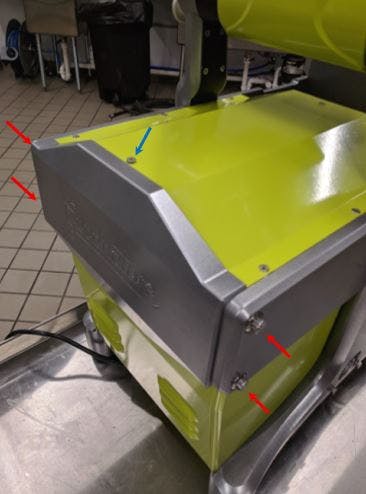
- Remove one (1) Phillips head screw from top panel using the #2 Phillips head screwdriver (blue arrow).
- Remove four (4) ⅜” 12-point drive fasteners from nameplate using the ⅜” combination wrench (red arrows) NOTE: Keep hand on plate when un-fastening as the panel will fall once all five screws are removed.
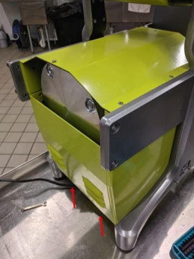
Back Panel Removal
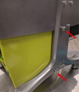
- Remove two (2) flange head screws on the bottom, rear side of the machine using the ¼” combination wrench.
- Gently pull panel towards you and pull down until it slides off of the machine.
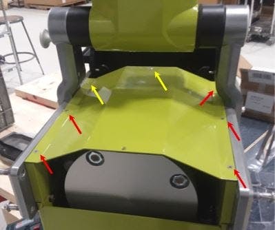
Top Panel Removal
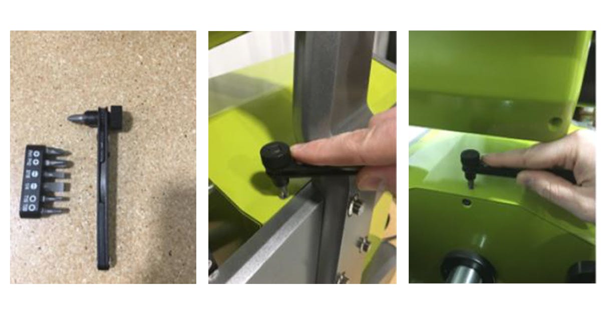
- Remove the remaining seven Phillips head screws on the top panel using the #2 Phillips head screwdriver. NOTE: The red arrows indicate screws that can be removed using a regular screwdriver. The two yellow arrows indicate the two (2) screws that will require the ¼” ratchet and the PH2 Phillips bit as shown in the following pictures.
- After screws are removed, pick up front edge of the top panel and slide top panel out the back side of the machine.
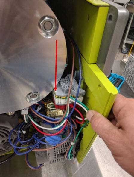
Electrical Connection
1. Before going further, check for loose electrical connections at the PS connection (see image below) NOTE: A loose electrical connection can mimic symptoms of a power supply failure.
2. If instructed by Goodnature, check the connection directly at the motor by following the Grinder Top Cover Removal procedure.
3. If a loose electrical connection is not found, then proceed to unplug all four electrical connection on the side of the machine (these should be numbered, however, if they are not, please number them for re-installation).
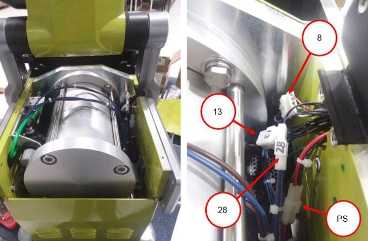
4. Unplug the remaining electrical connections labeled as shown in the pictures below (again, all connections should be labeled for re-installation).
Side Panel Removal
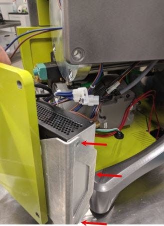
1. Using the ⅜” combination wrench, remove two (2) fasteners (red arrows) from the frame.
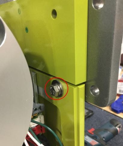
2. There may be a bolt on the inside of the panel that will need to be removed as well. Do this using the ⁷⁄₁₆” combination wrench. If this screw is not present, please ignore this step.
3. Slide electrical panel out of the back side of the machine; use care when sliding panel back as tugging hard can cause damage.
4. When sliding the panel back out of the machine, the gray component indicated below (red arrow) may need to be pushed down slightly to clear the large cylinder.
5. If there is resistance, make sure that all electrical connections are unplugged, and the two (2) side bolts are fully removed.
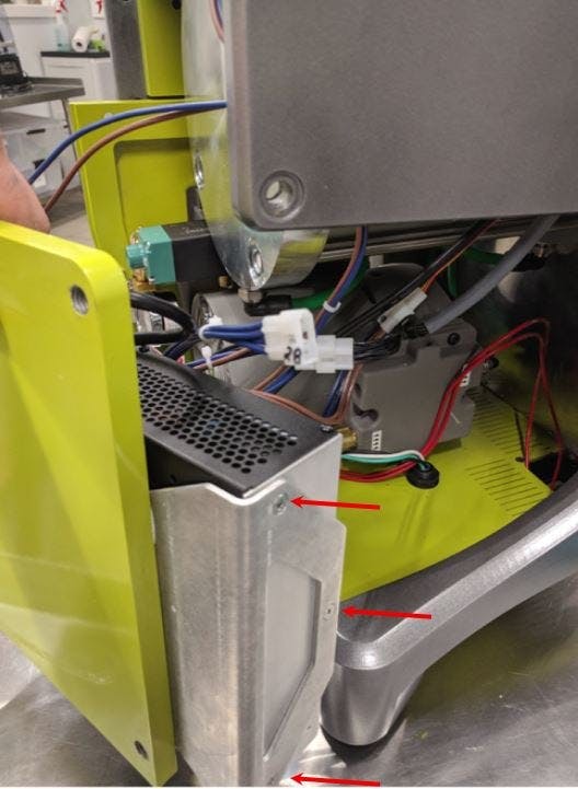
Power Supply Removal
1. Using the #2 Phillips head screwdriver, remove three (3) Phillips head flat head screws from back side of the panel to free the power supply (red arrows).
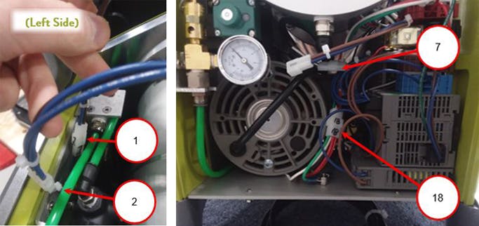
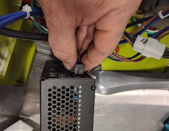
2. Disconnect the two (2) electrical cords from the power supply. Pinch connectors to remove as shown below.
Installation of New Power Supply
1. Install the connectors into the new power supply. NOTE: check to make sure these connectors are firmly secured in the power supply by lightly tugging on the plug to make sure nothing is loose.
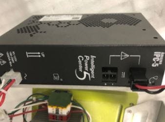
2. Place the new power supply back on to the bracket as shown.
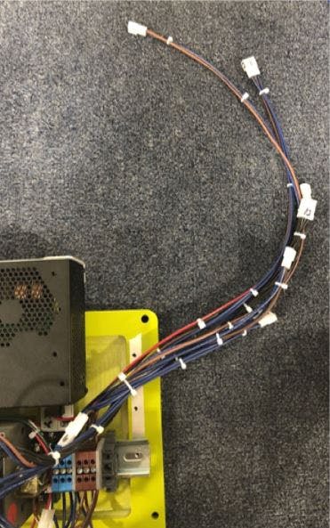
3. As you begin to install the electrical panel into the machine, group together the six (6) wires that connect on the top of the machine, and keep them upright.
4. If your machine had the bolt installed inside the machine as shown below, reinstall this bolt.
5. Connect the four (4) cables on the top right of the machine according to the labeled numbers.
6. Connect the two (2) cables on the top left of the machine according to the labeled numbers.
7. Connect the two (2) cables on the back of the machine according to the labeled numbers.
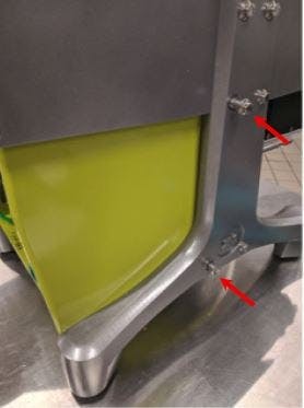
8. Install the two (2) bolts on the outside of the machine as shown below. Do not force the bolts, start them by hand and finish installing with the wrench.
9. Install the back panel by putting it into place on the machine, then start the screws by hand. Finish tightening both screws with the ¼” ratchet until snug. Do not over tighten.
10. Install the top panel. The panel has a front and back. Make sure the hole in the front middle lines up. If it does not line up, the panel needs to be spun around 180°. Remember to use the ¼” ratchet and the PH2 Phillips bit to install the two (2) screws (yellow arrows).
11. Install the rear nameplate. Lift the plate into place on the machine and start all four (4) bolts by hand and tighten as much as you can before using the ⅜” combination wrench to finish tightening (red arrows). Once the four (4) bolts are tight, install the final screw using the #2 Phillips head screwdriver (blue arrow).
Test to Make Sure the Machine Is Functioning Properly
For additional technical support needs, contact our technical support team. To order new parts and press bags, visit the X-1 Mini parts page.